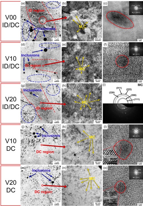
图(a)-(i)分别表示 V00、V10 和 V20 PWHT 碳膜复型样品中析出相的TEM明场和高分辨图像,揭示了不同尺寸和结构的析出相的分布。大尺寸析出相(100-400 nm)主要在枝晶干区域检测到,如蓝色虚线轮廓所示(图(a)、(d)和(g))。 大的椭圆形和条形碳化物是 M3C(M = Fe、Mn 和 Cr),具有正交结构。为了研究枝晶间区域的析出行为,图(a),(d)和(g)中红色圆圈标记的枝晶间区域的进一步放大图像分别如图(b),(e)和(h)所示。 V00、V10 和 V20 试样的枝晶间处析出相在面积分数和结构方面存在明显差异。如图(b)所示,在 V00 样品的枝晶间区域,纳米级析出相的尺寸约为 10 nm。另一方面,在 V10 和 V20 样品的枝晶间区域,纳米级析出相的尺寸大约小于 10 nm,如图(e)和(h)所示。图(c)显示了长 22 nm、宽 10 nm 的纳米级析出相的TEM高分辨图像。相应的快速傅里叶变换 (FFT) 如图 (c) 中的插图所示,表明在 V00 PWHT 试样的枝晶间区域成核的纳米级析出相是具有六方密堆积结构的 M2C(M = Mo,主要是)碳化物。然而,纳米级析出相的TEM高分辨图像和 FFT(图(f))和图(i)中所示的多晶衍射圆环显示,在 V10 和 V20 PWHT 试样中的枝晶间区域成核的纳米级析出相是MC(M = V,主要)具有NaCl型晶体结构的碳化物而不是M2C碳化物。注意到纳米级 M2C 碳化物的面积分数低于在枝晶间区域成核的纳米级 MC 碳化物,因为 MC 碳化物的成核率更高。图(j)和(m)中红色圆圈标记的枝晶干区域内部的两个放大视图(图(k)和(n))表明,在枝晶干区域周围还存在少量纳米级MC碳化物。 V10 和 V20 PWHT 试样中枝晶干区域的大尺寸 M3C 碳化物。根据这些观察,发现几乎所有的 M3C 碳化物都在枝晶干区域析出,而纳米级 M2C 或 MC 碳化物主要在枝晶间区域析出。图(l)和(o)分别显示了 V10 和 V20 PWHT 样品中位于枝晶干区域的两种纳米级 MC 沉淀物的TEM高分辨图像,尺寸分别为 11.3 ± 0.6 nm 和 6.8 ± 0.4 nm。基于 (200) 的面间距,11.3 ± 0.6 nm 和 6.8 ± 0.4 nm MC 碳化物的晶格参数分别为 0.424 nm 和 0.416 nm。可以合理地假设 V 元素含量和 MC 碳化物尺寸的差异会导致计算的晶格参数略有不同。此外,与枝晶干区域相比,V10和V20 PWHT样品在枝晶间区域析出的纳米级MC碳化物的面积分数显着增加(图(e),(h),(k)和(n)) 。已有文献证明,VC 碳化物优先形成于富 V 区,导致枝晶间和 枝晶干之间的不均匀分布。不同区域形成的不同尺寸碳化物的分布表明合金元素的偏析与碳化物的形成之间可能存在相关性。
Fig (a)–(i) represent the TEM BF and HRTEM images of the precipitates in V00, V10, and V20 PWHT carbon extraction replicas, respectively, revealing the distribution of precipitates with different size and structure. The large-size precipitates (100–400 nm) were mainly detected at DC region, as indicated by the blue dashed outlines (Fig (a), (d) and (g)). The large ellipsoid-shaped and strip-shaped carbides were M3C (M = Fe, Mn, and Cr) with orthorhombic structure. To investigate precipitation behavior at ID region, the further magnified images of ID region marked by the red circles in Fig (a), (d) and (g) are illustrated in Fig (b), (e) and (h), respectively. There were distinct differences among ID precipitates of V00, V10, and V20 specimens with regard to the area fraction and structure. As shown in Fig (b), at ID region of V00 specimen, the size of the nano-scale precipitates was approximately 10 nm. On the other hand, at ID region of V10 and V20 specimens, the size of the nano-scale precipitates was approximately less than 10 nm, as shown in Fig (e) and (h). Fig (c) shows a HRTEM image of a nano-scale precipitate with a size of 22 nm in length and 10 nm in width. The corresponding fast Fourier transform (FFT) shown as inset in Fig (c) indicated that the nano-scale precipitate nucleated at ID region in V00 PWHT specimen was the M2C (M = Mo, mainly) carbide with hexagonal, close-packed structure. However, the HRTEM image and FFT of a nano-scale precipitate (Fig (f)) and the polycrystalline diffracted circular rings shown in Fig (i) revealed that the nano-scale precipitates nucleated at ID region in V10 and V20 PWHT specimens were the MC (M = V, mainly) carbides with NaCl-type crystal structure instead of M2C carbides. Noting that the area fraction of nano-scale M2C carbides was lower than nano-scale MC carbides nucleated at ID region, owing to the greater nucleation rate of MC carbide . The two enlarged views (Fig (k) and (n)) of the interior of DC region marked by the red circles in Fig (j) and (m) indicated that a small amount of nano-scale MC carbide was also present around the large size M3C carbides at DC region in V10 and V20 PWHT specimens. According to these observations, it was revealed that almost all the M3C carbides precipitated at DC region, whilst the nano-scale M2C or MC carbides mainly precipitated at ID region. Fig (l) and (o) show the HRTEM images of two nano-scale MC precipitates located at DC region with the size of 11.3 ± 0.6 nm and 6.8 ± 0.4 nm in V10 and V20 PWHT specimens, respectively. The lattice parameter was 0.424 nm and 0.416 nm for the 11.3 ± 0.6 nm and 6.8 ± 0.4 nm MC carbides based on the interplanar distance of (200), respectively. It is reasonable to assume that the difference in V element content and size of the MC carbides could result in the slight difference of the calculated lattice parameter. In addition, the area fraction of the nano-scale MC carbides precipitated at ID region in both the V10 and V20 PWHT specimens were significantly increased compared with DC region (Fig (e), (h), (k) and (n)), respectively. It is well documented that VC carbides preferentially formed in rich zones of V , which resulted in the heterogeneous distribution between ID region and DC region. The distribution of carbides of different sizes formed at different regions suggested that there was a possible correlation between the segregation of the alloying elements and the formation of carbides.